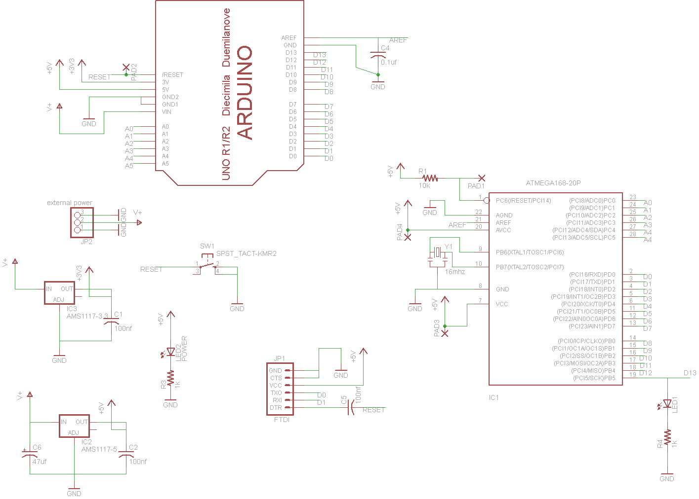
Well just as expected I woke up, reviewed my layout/schematic and had a few revelations. I decided to add a 3.3v regulator to the board and that proved to be a tricky task. For the regulators I am using cheap AMS1117’s, they have a pretty high voltage drop (around 1v) which makes them less then ideal, but they are good enough for this.
The updated schematic is as fallows. I also used a 3 pin external power connector to connect two grounds together where I couldn’t find another way. That makes a total of 3 jumper wires, the longest of which being the RESET.
One really great thing I learned in Eagle is the “naming” tool. If you name any two or more wires in the schematic it will ask you if you want them connected on the board! This makes it a lot easier to look at the schematic without tons of wires everywhere that you have to follow like a maze.
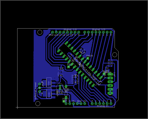
The PCB layout is pretty simular to the last one. The key here was to make it easy to toner transfer even if you’re new at the whole process (like me).
Assembly is rather straight forward. The longest part was drilling all the holes, I need to work on something better for doing that.
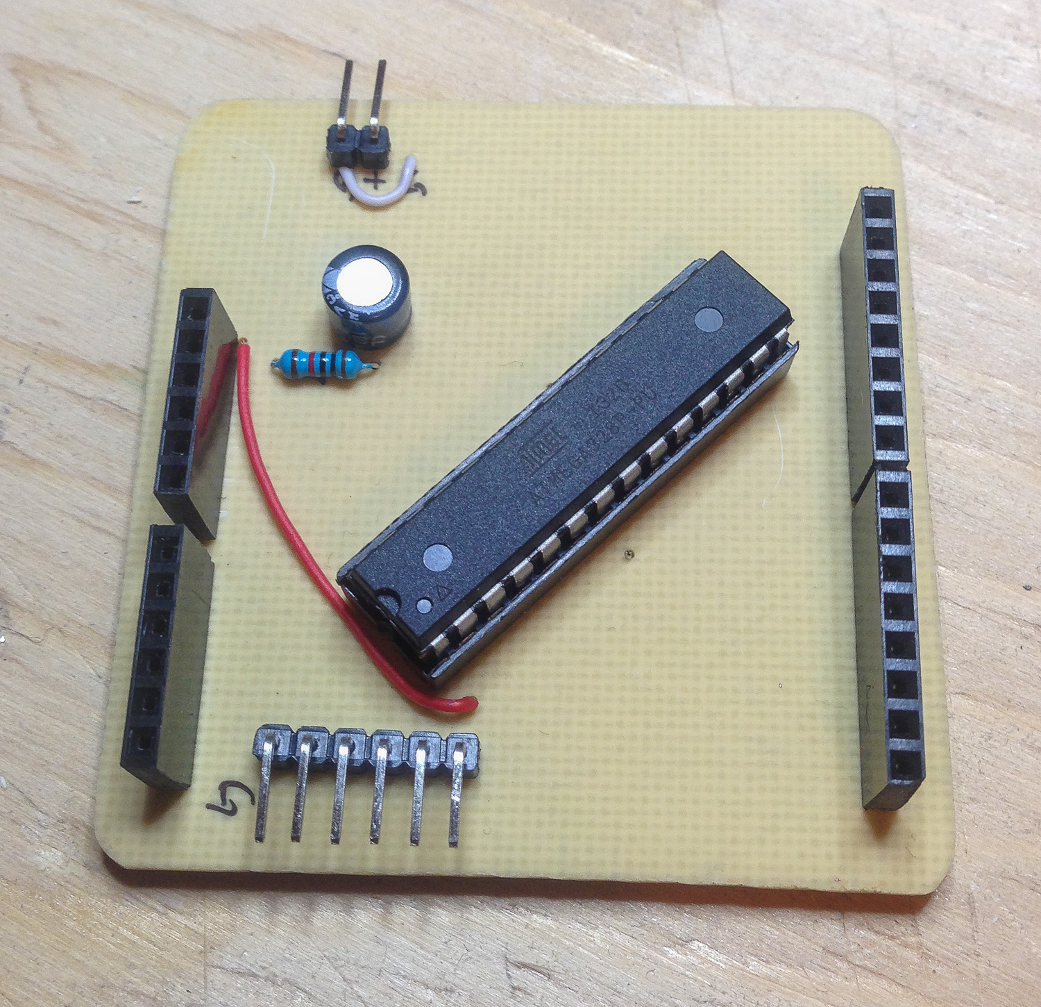
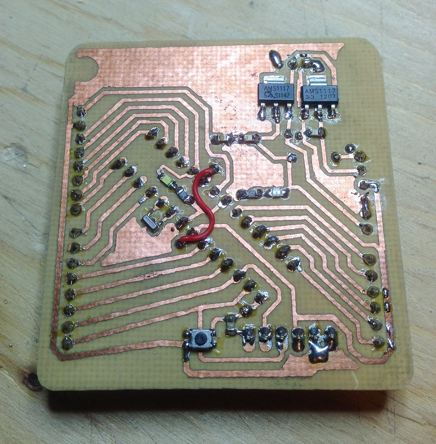
Using mostly surface mount parts (and a minimal amount of them) makes soldering this board a breeze.
Its ALIVE! here we are running the Blink sketch from the Arduino software. All is good!
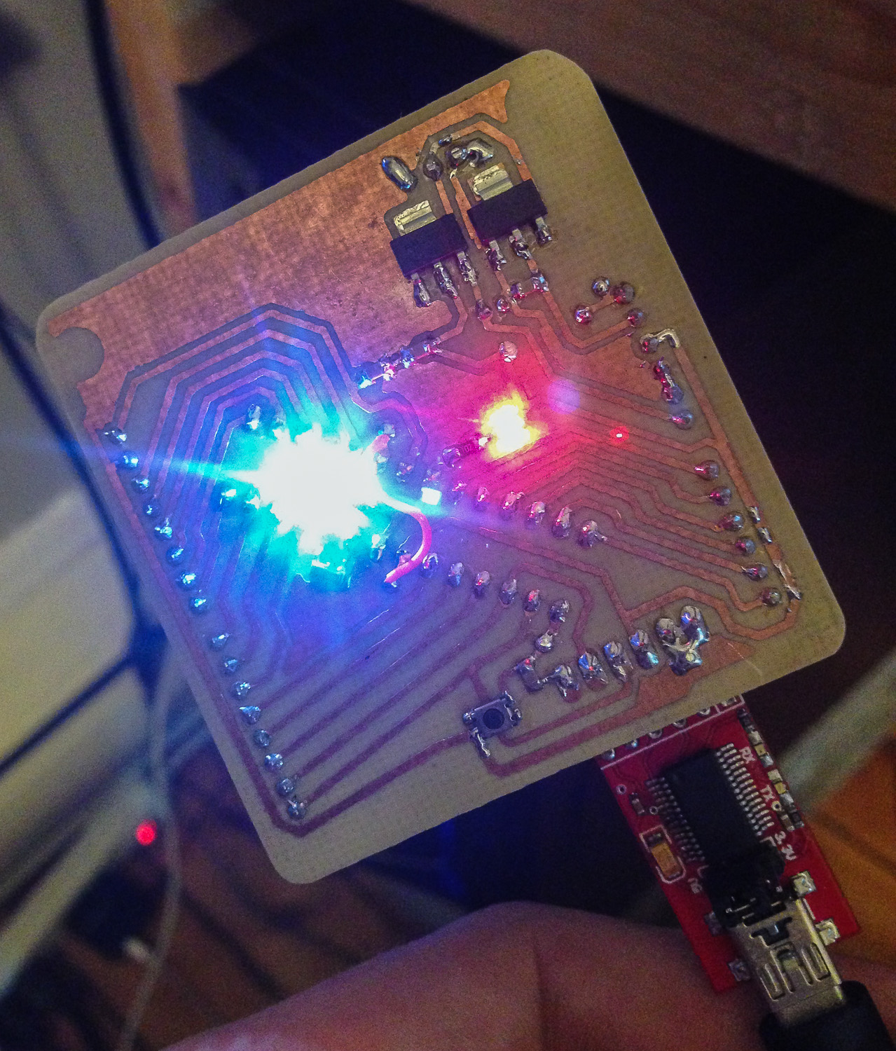
I did have one problem though. I plugged the power in backwards once and fried the two regulators! D’oh! I will have to look into Reverse Polarity Protection and find a good way to implement it into the PCB layout. Other then that though, I am happy. It works how it should, it didn’t take me THAT long, and it was cheap. I love DIY!