So the biggest thing in RC these days (air and land) is 2.4ghz. A few years ago it all moved from the days of crystals and 72mhz to the new frequency. The best, and worst, thing about it is that you no longer have to worry about what frequency everyone else is flying on (to a certain extent of course). The reason for this is that with the new bandwidth of 2.4ghz each company has introduced its own protocol, some even with frequency hopping, to keep the signals separate and glitch free. The reason why this sucks for the Regular Joe is because once you buy into a system you have to stick with their system (and prices). Lucky for us cheapos and hackers, the DIY community has been hard at work and most of the protocols have been hacked! I am using one hacked TX (transmitter) with 2 different modules that can work on nearly 10 different protocols! (Check it out HERE).
My friends arent so lucky though and they have Spektrum systems. What to do when we all wanted to buy the same quad copter that comes with a very limited TX almost too small to even use? While I had no problems because my TX already supports the protocol used (Hubsan), but not theirs. So I looked around and found just what I needed. A projects that uses a cheap RF module and an AVR to take a PPM output from any TX. More on that HERE and HERE.
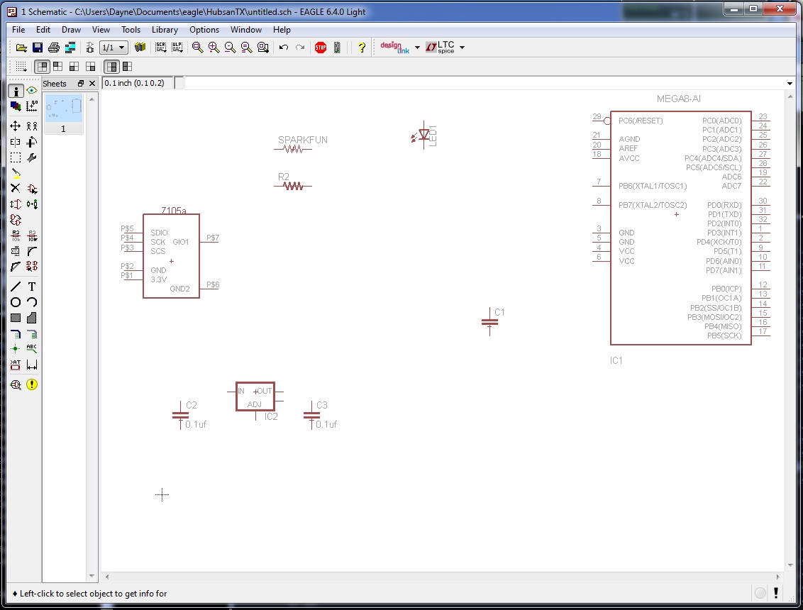
Now all that was left for me to do is lay out some PCB’s and build some modules! This is one of the first projects I’ve ever used home etched PCB’s for and also one of the first projects I’ve used Eagle Cad PCB software for! Should be a fun experience!
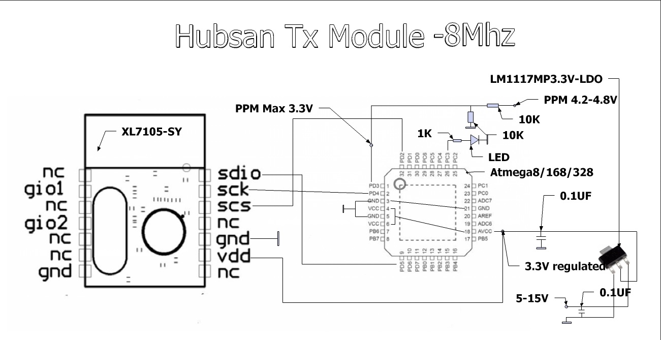
There’s the schematic I’m fallowing from the linked thread above, should be fairly straight forward!
Getting everything in order. I Started with the power supply, the module I’m using can’t take more then 3.3v!
After getting everything laid out how I liked, I printed the board and etched it! At this point I would like to show you the final schematic and layout, but we aren’t going to because of what comes next. I had a few “….oh I don’t really need that part” moments. First off, I thought “Hey! I’ll only need to program the chips once, no need for ISP”…. Yeah right. And also, “The version sans crystal will be good enough”. Oh how was I wrong!
The good news is, my etch was great, soldering the board was fine, and it all worked ok. That wasn’t good enough. First off I wanted the traces on the back with the module on the opposite side. While for some reason, the Eagle part for the module that I used is already mirrored. That means I have to mirror it again to put it on the top. This wasn’t the end of the world because I was able to mirror it in real life and still install it, but that’s not really good enough for me! Next is the crystal. Quads are fun to fly, but drift is annoying. If your quad thinks you are giving it input and in fact you aren’t that’s even MORE annoying! So, back to the PCB software I go. In the meantime, at least I’ve got a proof of concept that works!
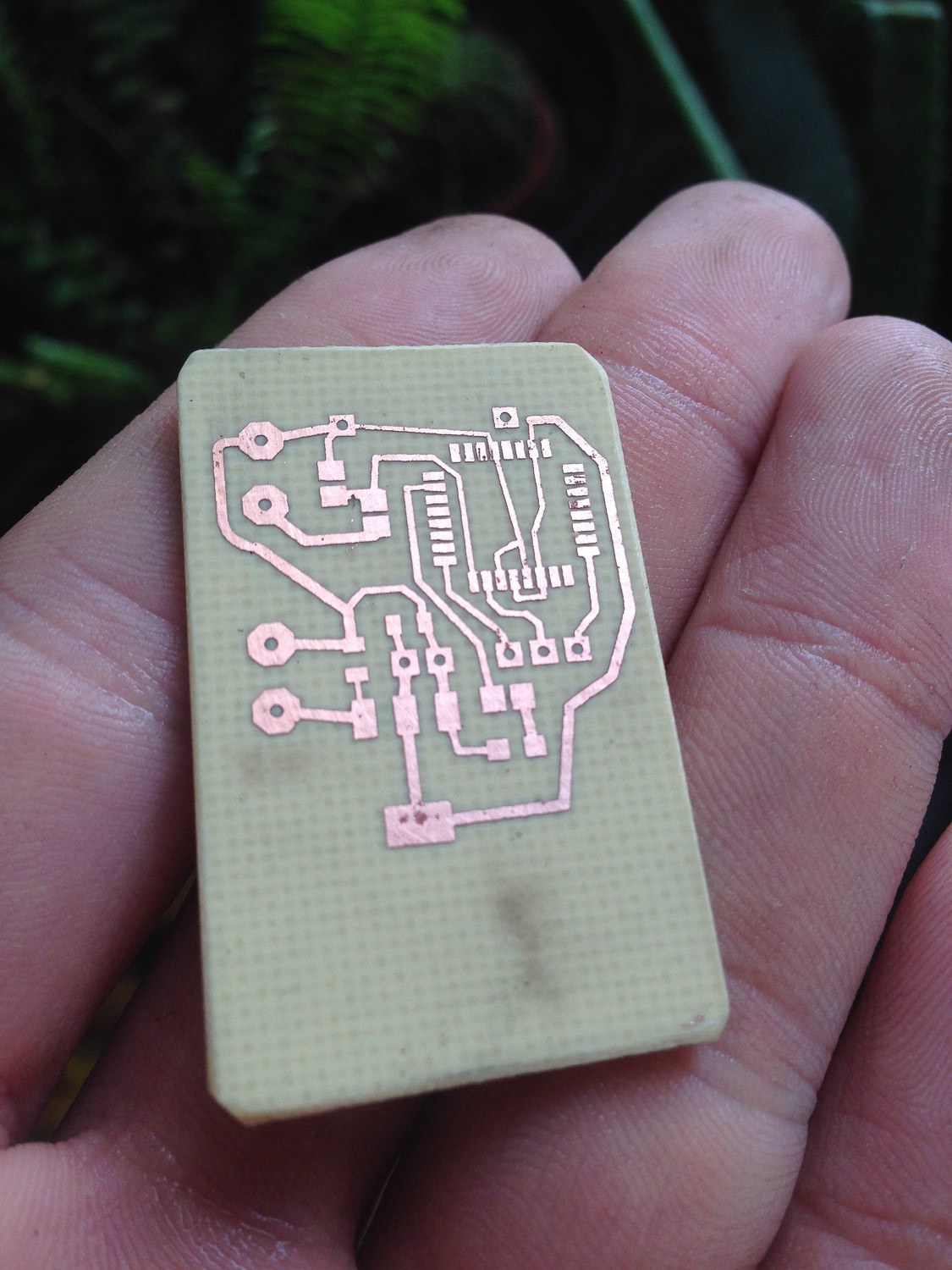
The pitting you see is actually because I am lazy. They only had double sided PCB so first I spray painted one side black, etched away the other side, and then removed the black and etched this side. Well the black got scratched before etching. My laziness, live and learn I guess. It didn’t cause any problems though.
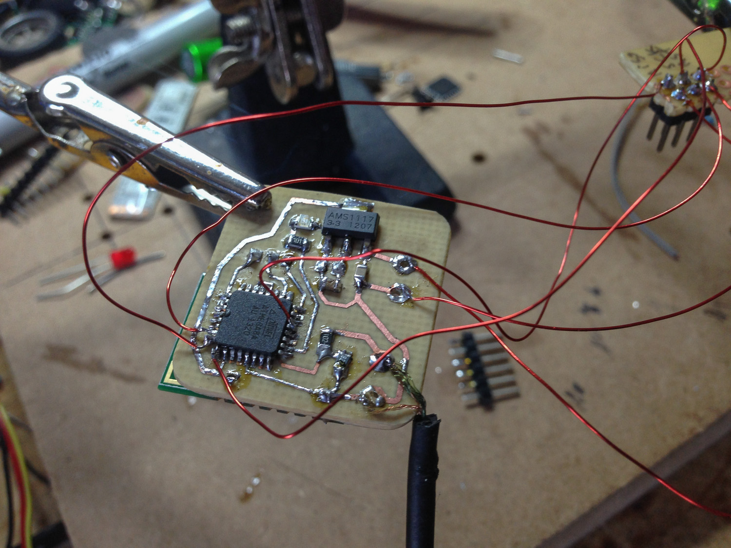
This is how we do it Ghetto Style; Magnet wire and a fine tipped soldering iron. It works…

Well it kinda works, too bad it’s not as good as I hoped! Time for REV.2!