Well, it’s been a while to say the least. I’ve been in BC over a year now, and I’m pretty set up in the geek/DIY department. I’ve taken on some crazy new projects (a car????) and I’ve been a part of other peoples projects.
In this last year:
Got my drivers license
Built a guitar tube amp
Built various guitar pedals
Swapped an engine in a 92 Honda Accord
Built a small rack to hold this server
upgraded my pi music player to Volumio with an i2s DAC
Built some braided CAT6 speaker cables
Started and built a prototype CMOS noise synth (more to come!)
Installed Arch Linux on an 80$ Thinkpad (took a while!)
Obviously I’ve done more then that, but those seemed like the most relevant and mention worthy feats…. not like anyone reads this. Anyway, I will try and kick my butt into gear and get posting stuff about project I’m working on.
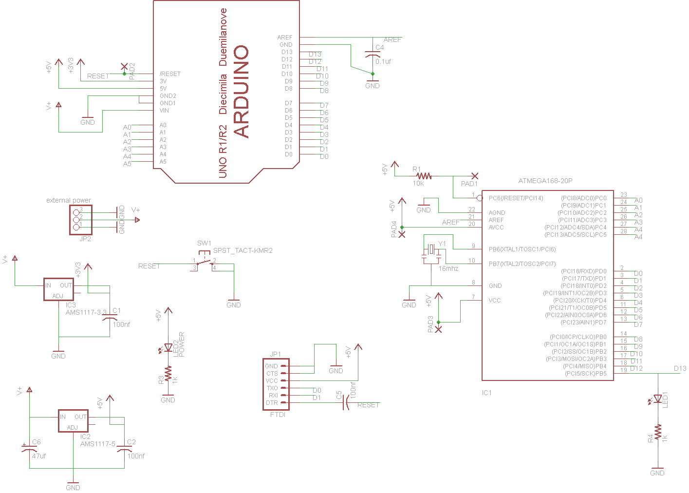
Well just as expected I woke up, reviewed my layout/schematic and had a few revelations. I decided to add a 3.3v regulator to the board and that proved to be a tricky task. For the regulators I am using cheap AMS1117’s, they have a pretty high voltage drop (around 1v) which makes them less then ideal, but they are good enough for this.
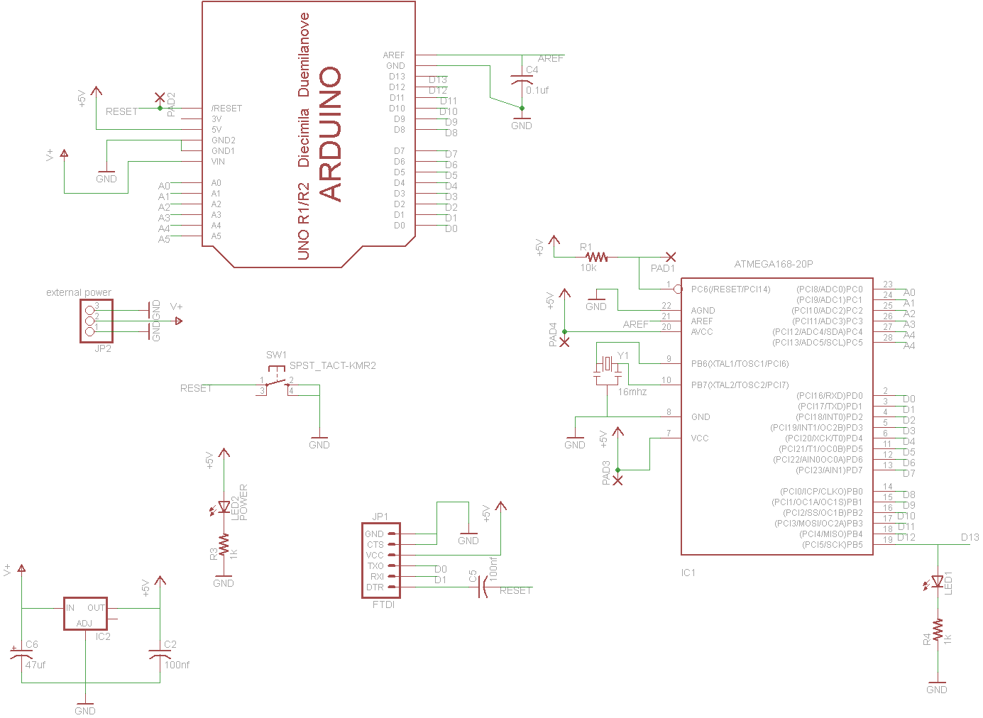
The updated schematic is as fallows. I also used a 3 pin external power connector to connect two grounds together where I couldn’t find another way. That makes a total of 3 jumper wires, the longest of which being the RESET.
One really great thing I learned in Eagle is the “naming” tool. If you name any two or more wires in the schematic it will ask you if you want them connected on the board! This makes it a lot easier to look at the schematic without tons of wires everywhere that you have to follow like a maze.
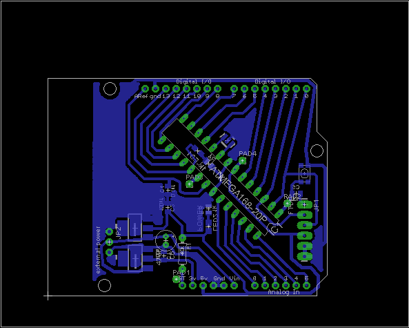
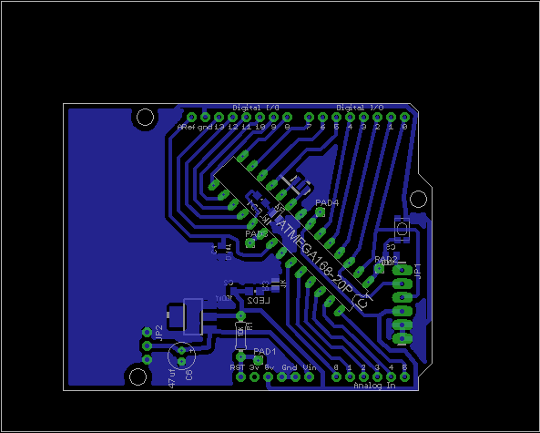
The PCB layout is pretty simular to the last one. The key here was to make it easy to toner transfer even if you’re new at the whole process (like me).
Assembly is rather straight forward. The longest part was drilling all the holes, I need to work on something better for doing that.
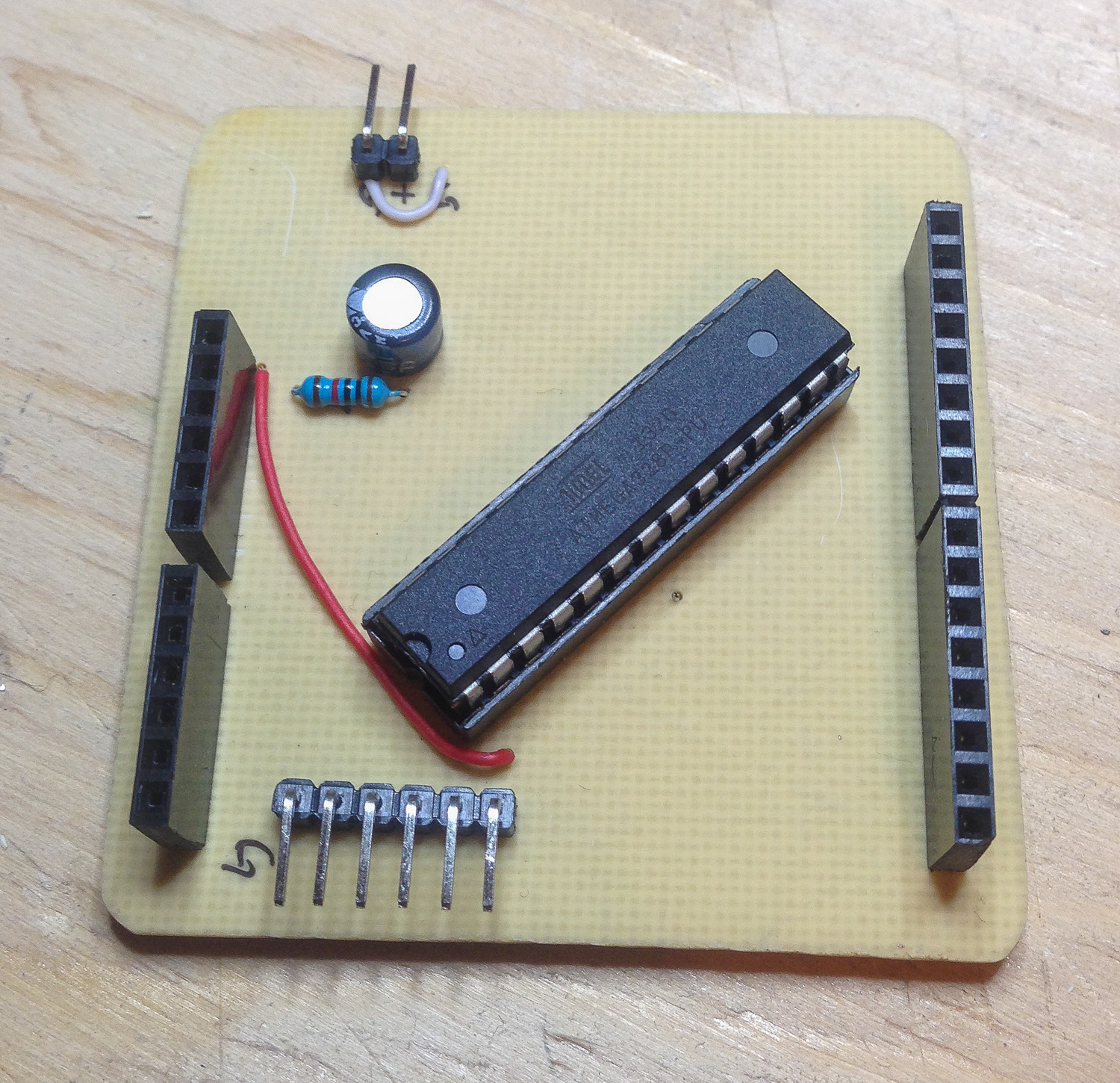
Dwuino prototype number 1 populated board.
Using mostly surface mount parts (and a minimal amount of them) makes soldering this board a breeze.
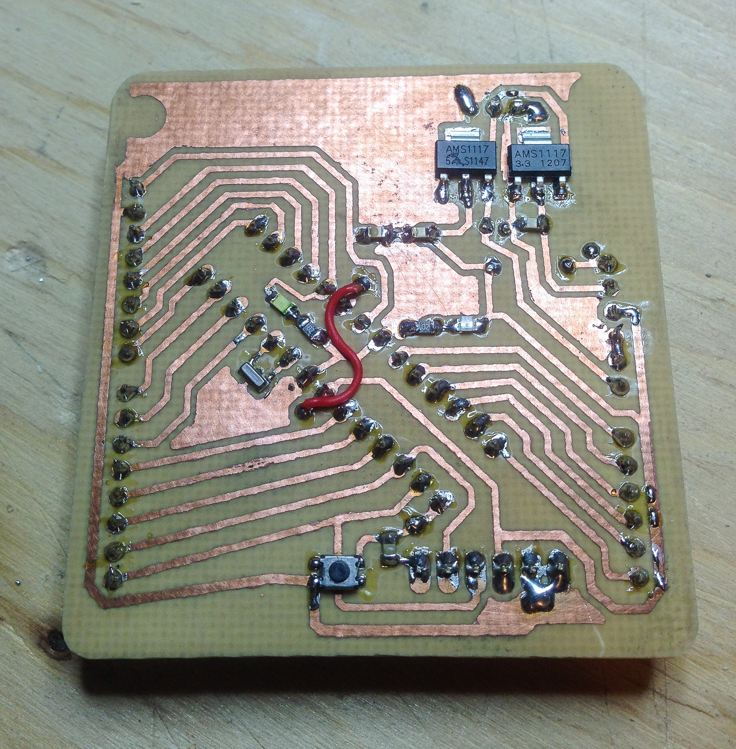
Dwuino prototype number 1 populated board bottom.
Its ALIVE! here we are running the Blink sketch from the Arduino software. All is good!
Dwuino prototype number 1 running the Blink sketch.
I did have one problem though. I plugged the power in backwards once and fried the two regulators! D’oh! I will have to look into Reverse Polarity Protection and find a good way to implement it into the PCB layout. Other then that though, I am happy. It works how it should, it didn’t take me THAT long, and it was cheap. I love DIY!
Well I love the Arduino. It makes all sorts of things possible. My only problem is I always run out of them! I decided it was time to remedy this problem by coming up with my own clone that I could easily build myself with components that were easy for me to source. I will be using mostly SMB components because I find them to be easier on home etched PCBs then drilling holes. Don’t worry though, there’s still TONS of holes to drill on an Arduino clone since I still want the headers!
I have planned on omitting the USB and going with a serial connection. There will also be no ISP, I will program the chips in another platform before hand. With the left over space maybe I will add a prototyping zone? Hmmm.
Credit goes to the Nanino, the only other Arduino Uno foot print home etch board I could find.
Well that’s enough chat, here it is so far:
First look at the PCBDWuino Schematic
More to come! I will sleep on it and go over the schematic and PCB layout again before I attempt the etch and assembly.
So the biggest thing in RC these days (air and land) is 2.4ghz. A few years ago it all moved from the days of crystals and 72mhz to the new frequency. The best, and worst, thing about it is that you no longer have to worry about what frequency everyone else is flying on (to a certain extent of course). The reason for this is that with the new bandwidth of 2.4ghz each company has introduced its own protocol, some even with frequency hopping, to keep the signals separate and glitch free. The reason why this sucks for the Regular Joe is because once you buy into a system you have to stick with their system (and prices). Lucky for us cheapos and hackers, the DIY community has been hard at work and most of the protocols have been hacked! I am using one hacked TX (transmitter) with 2 different modules that can work on nearly 10 different protocols! (Check it out HERE).
My friends arent so lucky though and they have Spektrum systems. What to do when we all wanted to buy the same quad copter that comes with a very limited TX almost too small to even use? While I had no problems because my TX already supports the protocol used (Hubsan), but not theirs. So I looked around and found just what I needed. A projects that uses a cheap RF module and an AVR to take a PPM output from any TX. More on that HERE and HERE.
Now all that was left for me to do is lay out some PCB’s and build some modules! This is one of the first projects I’ve ever used home etched PCB’s for and also one of the first projects I’ve used Eagle Cad PCB software for! Should be a fun experience!
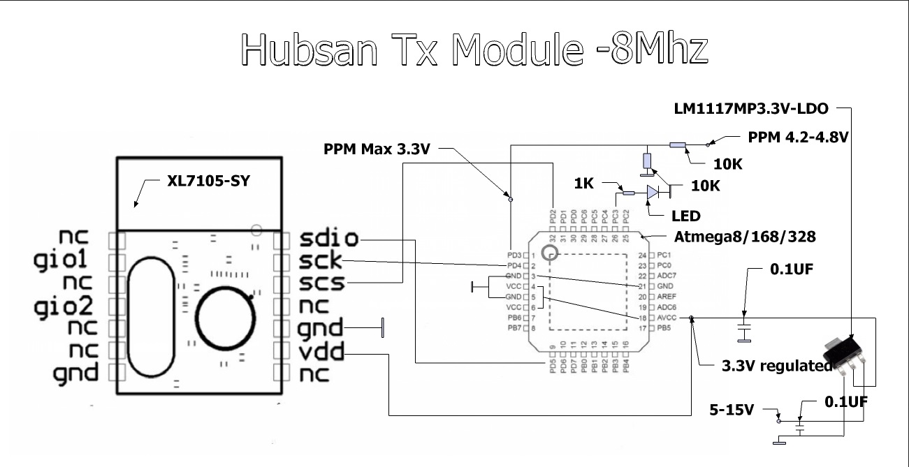
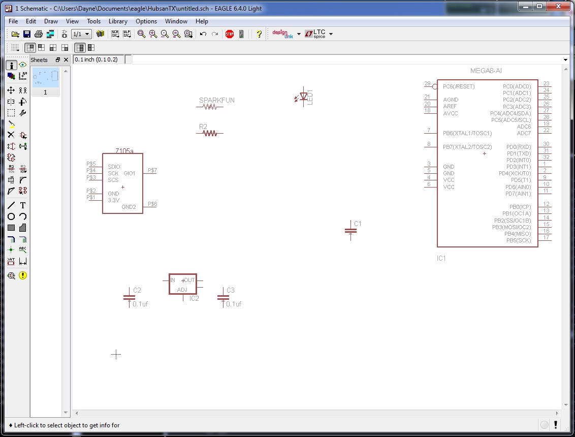
The schematic I am using for reference.
There’s the schematic I’m fallowing from the linked thread above, should be fairly straight forward!
First I get all my components out
Getting everything in order. I Started with the power supply, the module I’m using can’t take more then 3.3v!
After getting everything laid out how I liked, I printed the board and etched it! At this point I would like to show you the final schematic and layout, but we aren’t going to because of what comes next. I had a few “….oh I don’t really need that part” moments. First off, I thought “Hey! I’ll only need to program the chips once, no need for ISP”…. Yeah right. And also, “The version sans crystal will be good enough”. Oh how was I wrong!
The good news is, my etch was great, soldering the board was fine, and it all worked ok. That wasn’t good enough. First off I wanted the traces on the back with the module on the opposite side. While for some reason, the Eagle part for the module that I used is already mirrored. That means I have to mirror it again to put it on the top. This wasn’t the end of the world because I was able to mirror it in real life and still install it, but that’s not really good enough for me! Next is the crystal. Quads are fun to fly, but drift is annoying. If your quad thinks you are giving it input and in fact you aren’t that’s even MORE annoying! So, back to the PCB software I go. In the meantime, at least I’ve got a proof of concept that works!
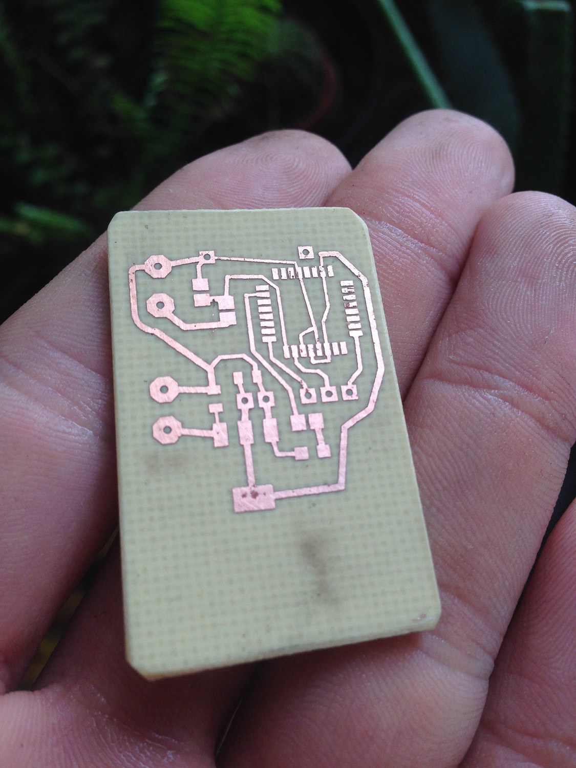
The etched board.
The pitting you see is actually because I am lazy. They only had double sided PCB so first I spray painted one side black, etched away the other side, and then removed the black and etched this side. Well the black got scratched before etching. My laziness, live and learn I guess. It didn’t cause any problems though.
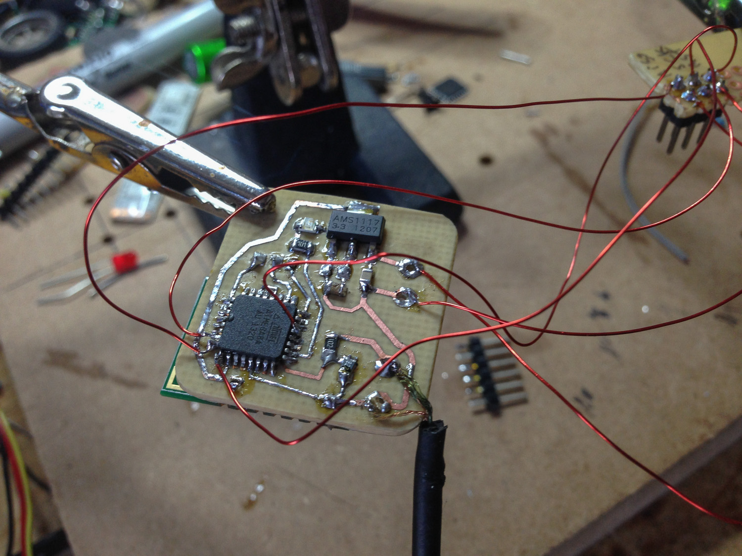
Some ghetto ISP
This is how we do it Ghetto Style; Magnet wire and a fine tipped soldering iron. It works…
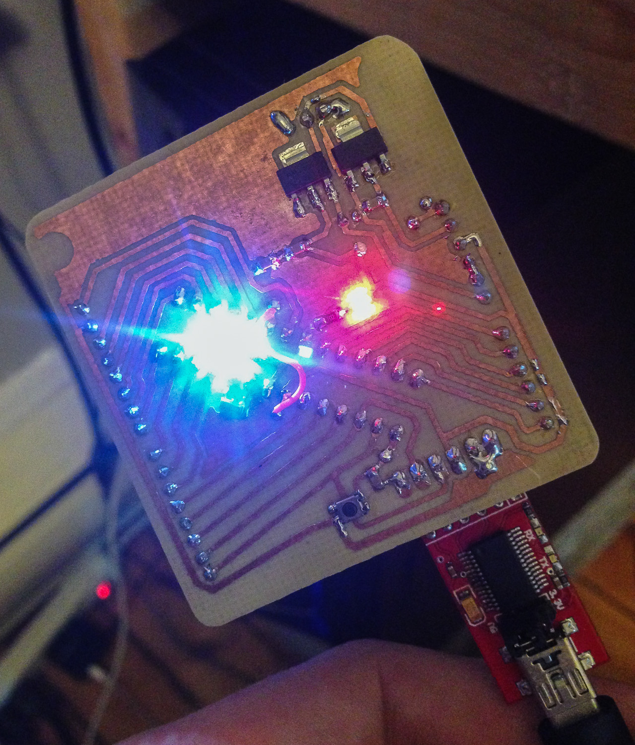
Green LED means we are bound!
Well it kinda works, too bad it’s not as good as I hoped! Time for REV.2!
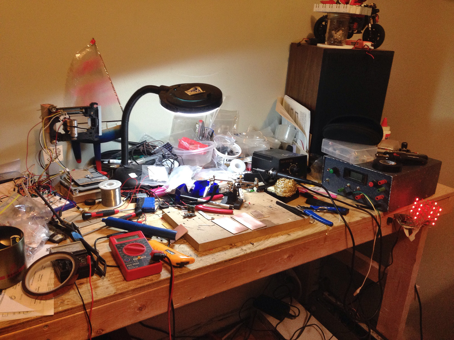
I figured it’s about time to move away from Blogger and actually get my projects out there. I’ve got a lot of random projects on the go and many more to come! Heck, you should see my work bench!